Honestly the only reason I got into this rabbit hole is having an old laptop lying around and wondered how far I can stretch the line without bricking it entirely. In particular to see how disk encryption actually works under the hood and trying to break it by clipping some cheap hardware hacking tools from AliExpress.
Special thanks to Xeno Kovah and OpenSecurityTraining2 for sparking my curiosity and providing some incredible quality material.
BitLocker 101: Keys, TPMs, and Cryptography
Lets walk through how BitLocker is supposed to work, because the more you understand the elegant design, the more the real world flaws start to make sense.
BitLocker represents Microsoft’s attempt to solve a genuinely hard problem: how do you automatically decrypt a hard drive when an authorized user boots their computer, but keep it locked when an unauthorized person tries to access the data?
The solution relies on a “trusted boot” process. Think of it as a chain of cryptographic measurements that starts with your computer’s firmware and continues through each piece of software that loads during startup. Each component hashes the next, creating a unique fingerprint of your system’s exact boot state.
How the Chain of Trust Works
It does so by using what’s called a Trusted Platform Module(TPM) chip, which only hands over the keys once the measured state matches the same state as when Bitlocker was first configured on the machine. If anything significant has changed in the boot process the TPM chip will not transfer the keys and may require a Bitlocker recovery process.
This measurement process creates what’s called a “root of trust” but like any chain, it’s only as strong as its weakest link. The TPM measures each component, but it has to trust that the measurements it receives are valid, and this is where the elegance starts to show cracks.
Who Measures the Measurer?
BitLocker’s security relies on a chain of trust, but there’s a logical issue at its core: the UEFI firmware measures everything else, but nothing measures the firmware itself when it first loads.
The TPM trusts whatever measurements the firmware sends it. If an attacker modifies the firmware to lie about those measurements, the TPM has no way to know. It will happily unseal the BitLocker keys as long as the firmware reports the “correct” PCR values - even if the actual boot process is completely compromised.
This is the “Static Core Root of Trust for Measurement” (CRTM) problem. The first code that runs is inherently trusted, with no way to verify its integrity from outside the system.
1 | Initial startup FW at CPU reset vector |
The Weakest Link: SPI Flash Memory
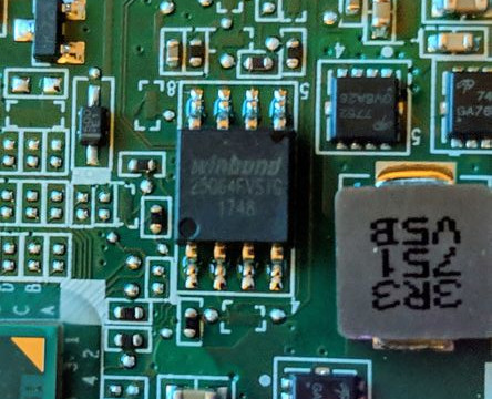
When your computer boots, the UEFI/BIOS firmware is the first code to run, responsible for measuring itself and the next component in the chain. But here’s the catch: the UEFI firmware lives in SPI flash memory which is a small chip that’s often easily accessible on the motherboard and wasn’t designed with sophisticated tamper protection in mind.
Exercise! Try looking at an old motherboard or any PCB you have lying around and find a small 8-legged chip and do a short google search on the text that’s written on it, most chip vendors provide an open source datasheet
This is where a cheap flash programmer comes into play, it can directly read and write the firmware stored in SPI flash. While the disk encryption keys themselves reside on the disk and are sealed to the TPM, a modified firmware that lies to the TPM or logs keys after the TPM unseals them can enable an attacker with physical access to recover those keys.
The irony is that BitLocker’s strength its tight integration with the hardware boot process also creates its most exploitable weakness. Every piece of the trusted boot chain becomes a potential attack surface for someone with physical access.
The $5 Attack: Hardware and Tools
The beauty of this attack is how accessible it is. You don’t need expensive equipment or a sophisticated lab setup. Everything you need can be ordered from AliExpress for under $5 and will arrive in a plastic bag with zero documentation.
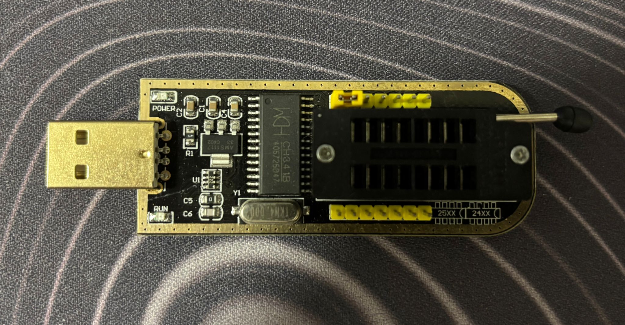
CH341A USB Programmer
This little board is your main tool. It’s designed for programming various flash chips and EEPROMs, but works perfectly for reading and writing SPI flash. The CH341A speaks SPI protocol and shows up as a USB device on your computer.
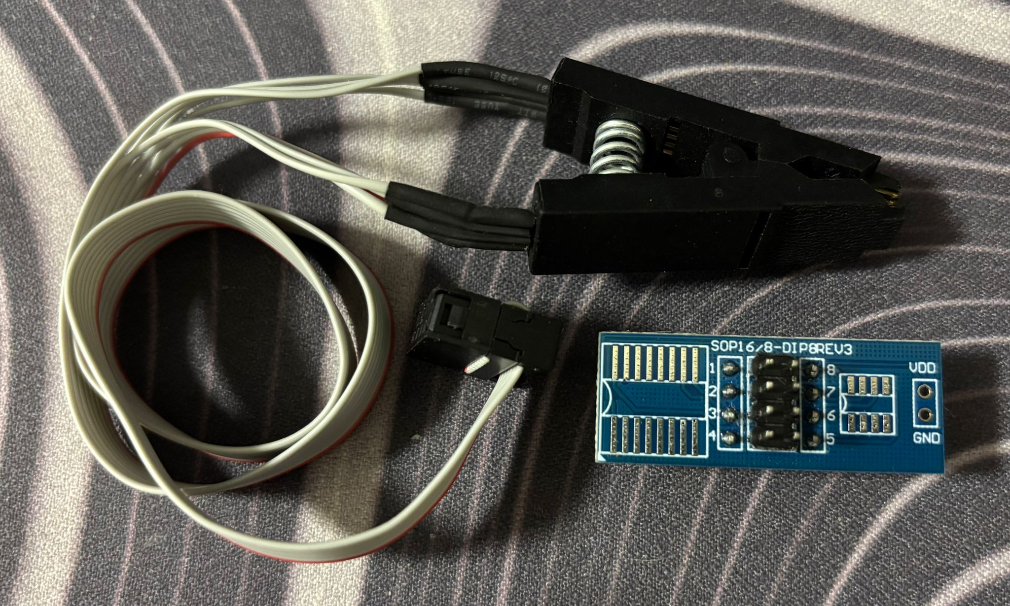
SOIC8 Test Clip
Also called a “Pomona clip” or “SOIC clamp”, usually arriving as a bundle with the flash programmer. This clips directly onto the SPI flash chip’s pinouts without desoldering, making the attack non-destructive and quick.
Reading the Flash
Most laptops make this almost too easy - you just need to pop off the bottom cover, no security screws, no tamper seals, nothing.
Once you’re in, you need to locate the SPI flash chip. The chip itself is typically SOIC-8 package, which is just a way of saying it has 8 legs and is surface mounted on the board.
Sometimes the chip is hiding under a cable or behind a metal EMI shield. In those cases, you might need to carefully move cables aside or remove a few more screws to access it. I’ve also seen chips positioned on the other side of the motherboard, which means you need to fully remove the board to access them - annoying but not impossible.
Connecting the Clip
The SOIC8 clip needs to be oriented correctly, the wire for pin 1 in this instance is colored in red for easy identification. And as for the chip pin 1 is almost always marked with a small dot in the corner, otherwise just refer to the datasheet. Get this wrong and you’ll either read garbage or potentially damage something onboard.
The pinout for a standard SPI flash chip looks like this:
1 | ┌────────┐ |
Software Setup
Plug in your CH341A programmer and verify it’s detected:
1 | flashrom -p ch341a_spi |
You should see output showing the programmer was found and detected the flash chip:
1 | flashrom v1.2 on Linux |
For an 8MB chip, this takes about 1-2 minutes. Flashrom reads the entire contents sequentially, block by block through the address space. The real trick here is verifying your dump is clean since flash reads can fail if the clip wasn’t seated perfectly, so always read twice and compare checksums.
1 | sudo flashrom -p ch341a_spi -r firmware_dump2.bin |
Matching checksums means we have a good dump, if not then try playing around with the clip or even reseating it completely. This is an integral part of the process to make sure we don’t get a corrupted dump that is practically worthless. Once we confirm the validity of the firmware we just dumped, backing it up is also crucial in case we end up bricking our board later on by writing bad firmware or doing some risky experimentation.
From Hardware Dump to Usable Data
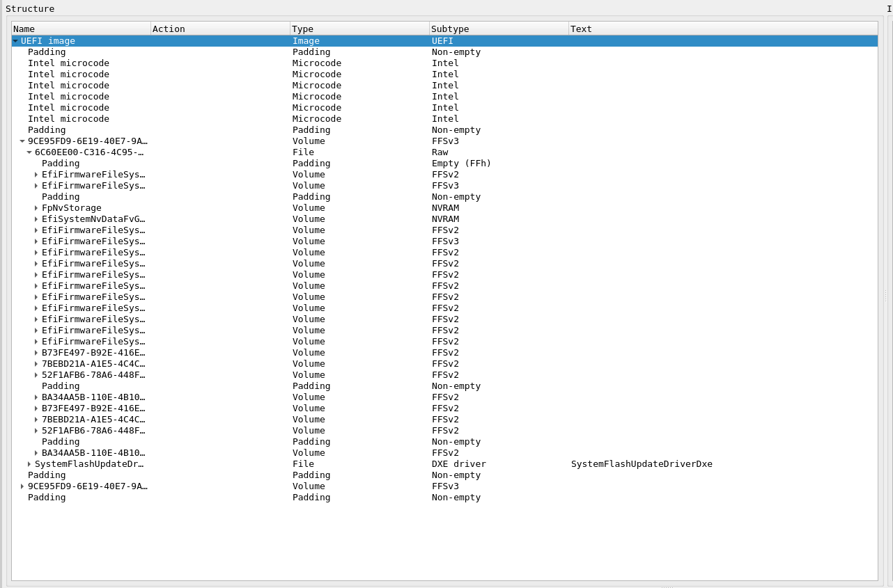
Looking at what was just extracted we are able to see a nested structure that contains everything the system needs to boot - think of it like a ZIP file containing other ZIP files, each with their own internal organization. UEFITool will parse the Intel flash descriptor layout with a nice GUI:
At the highest level, you’ll see the flash regions:
- Flash Descriptor Region - Defines the layout
- BIOS Region - Contains UEFI code and NVRAM
- ME Region - Intel Management Engine firmware
- GbE Region - Network controller config
- PDR Region - Platform data
The BIOS region is your target. Inside it, you’ll find:
- UEFI executable modules (DXE drivers, PEI modules)
- NVRAM Variable Store - This is where EFI variables live
- Boot configuration and settings
- Potentially BitLocker-related data
Extracting and Analyzing NVRAM
In UEFITool, right-click on an NVRAM volume (e.g., “EfiSystemNvDataFvGuid”), select “Extract body” to save just the NVRAM region. Now load the extracted NVRAM in UEFITool
1 | UEFITool nvram_extracted.bin |
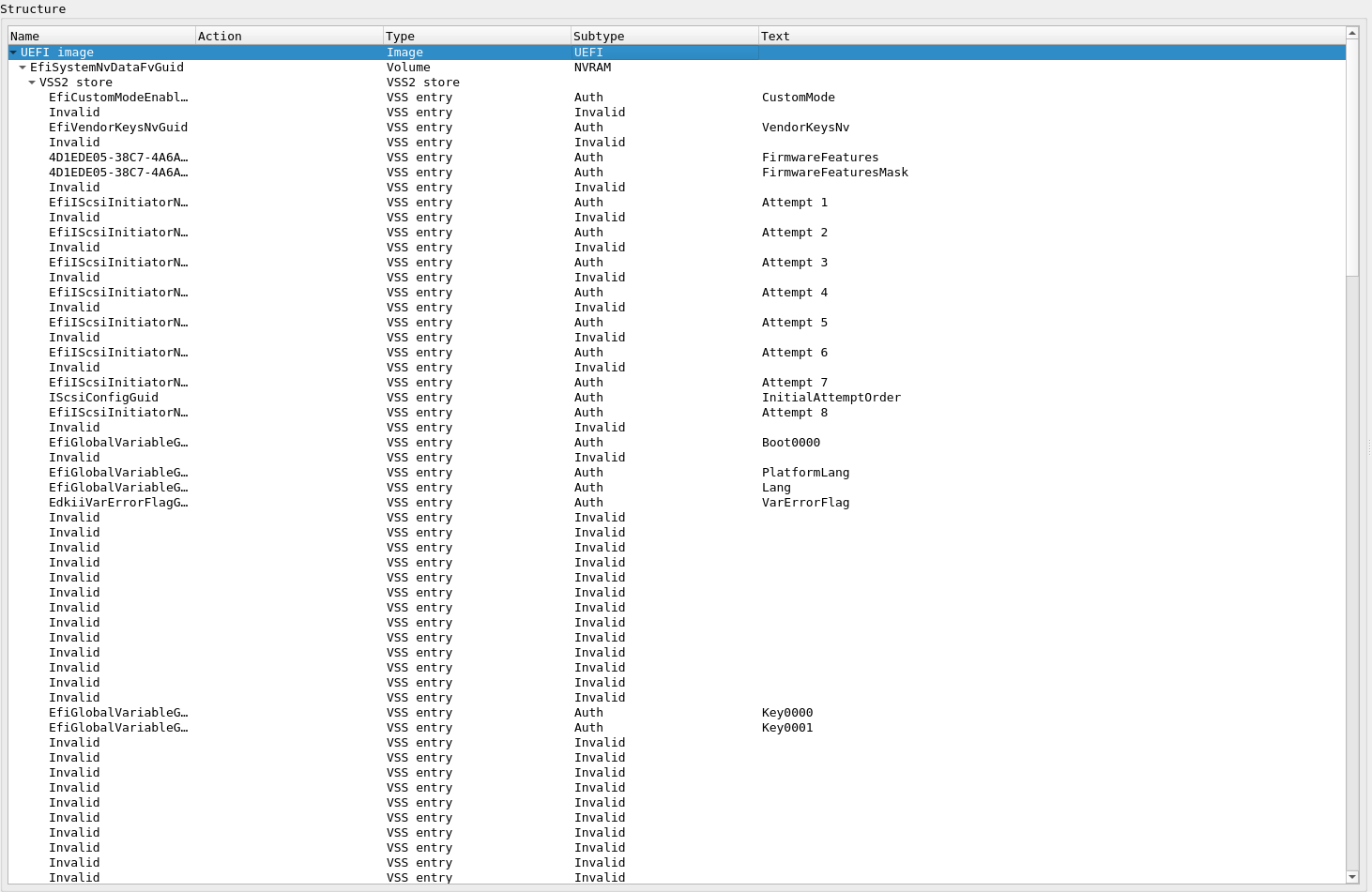
Now you see the actual EFI variables stored inside - this is what the firmware and OS use to communicate configuration:
What you’re looking at:
- VSS2 store - Variable Storage System format (the container)
- Individual variables (VSS entries):
CustomMode- Secure Boot custom mode settingVendorKeysNv- Vendor key statusFirmwareFeatures/FirmwareFeaturesMask- Platform capabilitiesEfiIScsiInitiatorNameProtocolGuid- iSCSI boot configurationIScsiConfigGuid- iSCSI settingsBoot0000,Key0000,Key0001- Boot and key configurationPlatformLang,Lang- Language settingsVarErrorFlag- Error tracking
Now you see the actual EFI variables - boot configuration, Secure Boot keys, platform settings. The “Invalid” entries show deleted variables that persist in firmware dumps. Old data isn’t immediately erased, just marked invalid.
For the attack itself, deep analysis isn’t necessary - we just need to modify the firmware to lie about PCR measurements. But understanding the structure helps avoid bricking the system when making modifications.
Flash Memory Protection
Before we try modifying firmware, let’s understand what’s supposed to protect it. Modern Intel platforms have hardware protection mechanisms defined in NIST SP 800-147 “BIOS Protection Guidelines”. These are registers in the chipset designed to prevent unauthorized firmware modification.
BIOS_CNTL - BIOS Control Register
This 8-bit register (offset DCh in LPC I/F) controls firmware write access:
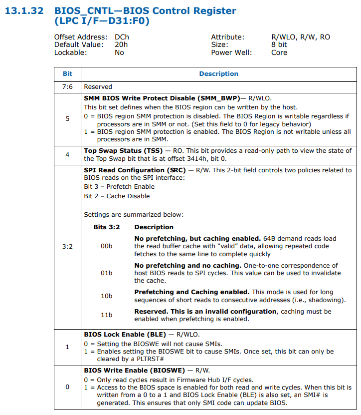
Bit 5: SMM_BWP (SMM BIOS Write Protect)
0= BIOS region SMM protection is disabled1= BIOS Region is NOT writable unless all processors are in SMM
Bit 1: BLE (BIOS Lock Enable)
0= Setting BIOSWE will not cause SMIs1= Setting BIOSWE generates SMI to trap unauthorized writes
Bit 0: BIOSWE (BIOS Write Enable)
0= Firmware is read-only1= Firmware is writable
PR0-PR4 - Protected Range Registers
Five 32-bit registers (SPIBAR + 74h through 84h) define memory regions that should be protected:
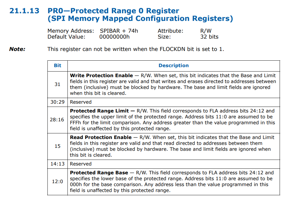
Bit 31: WPE (Write Protection Enable)
0= Writes/erases to this range are allowed1= Writes/erases to this range are blocked by hardware
Bit 15: RPE (Read Protection Enable)
0= Reads from this range are allowed1= Reads from this range are blocked by hardware
Bits 28:16: Protected Range Limit
- Defines the upper boundary of the protected region
Bits 12:0: Protected Range Base
- Defines the lower boundary of the protected region
The Reality: Protection Often Disabled
Research has shown that many systems ship with these protections entirely disabled - all registers set to 0x00. On those systems, firmware is writable from the OS without any hardware programmer needed. But even on properly configured systems, these protections only defend against software-based attacks.
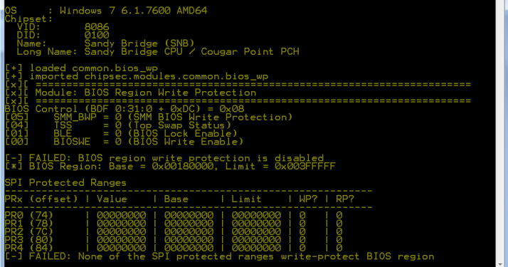
When you physically clip onto the SPI chip with a CH341A, you bypass the chipset entirely. The protection registers have no effect because they only control access through the chipset’s memory controller.
What protection registers defend against:
- Malware trying to flash BIOS from the OS
- Unauthorized software updates
- Rootkits attempting persistence
What they don’t defend against:
- Physical access to SPI flash chip
- Hardware programmer attacks
- Evil Maid scenarios
Modifying the Firmware
Now that we have the firmware dump and understand the (lack of) protections, let’s look at how an attacker would modify it.
You might assume firmware images are cryptographically signed and verified before execution, making modification impossible. However this is not the case for most systems.
NIST SP 800-147 “BIOS Protection Guidelines” actually specifies that firmware updates should be authenticated:
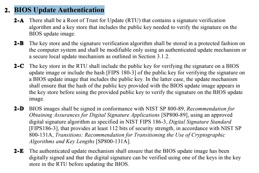
What is actually signed:
- Individual UEFI drivers and applications (PE32+ executables)
- OS bootloaders verified by Secure Boot
- Option ROMs from expansion cards
What isn’t signed:
- The complete firmware image as a whole
- The flash descriptor and layout
- NVRAM variable storage
- Early boot code (SEC/PEI phases)
- the code that does the signature verification
This asymmetry is critical. Secure Boot verifies that bootmgfw.efi is signed by Microsoft, but nothing verifies the firmware code that performs this check. An attacker can modify the verification routine itself.
Without a hardware root of trust, the firmware is the first code to execute and must be trusted by definition. There’s no external verifier watching it boot.
What Needs to Be Modified
The attack targets the early boot code that performs TPM measurements. Specifically, we need to patch the functions that extend PCR values. When the firmware measures itself and reports to the TPM, we want it to report the original hash instead of the actual (modified) hash.
The firmware measures itself and reports the measurement to the TPM. If we modify the firmware to lie about what it measured, the TPM has no way to verify the claim.
The Attack Flow
1 | Physical Access |
Understanding BitLocker Configuration
For the attack to work, the modified firmware needs to know which PCRs protect the BitLocker keys. In an actual attack, the payload would extract this information automatically during boot. Here’s what that data looks like:
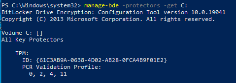
The payload reads this from BitLocker metadata and knows it needs to forge measurements for four specific PCRs:
| PCR | What Gets Measured |
|---|---|
| 0 | UEFI firmware code |
| 2 | Option ROM drivers |
| 4 | Boot Manager |
| 11 | BitLocker access control |
PCR[0] is the primary target - this is where the firmware’s own hash gets measured. If the payload can lie about this value, the rest of the chain doesn’t matter.
Why Firmware Modification Works
The attack succeeds because of a fundamental architectural flaw we explained at the start:
1 | Expected Behavior |
The TPM has no way to verify the firmware’s claims. It receives measurements and trusts them - there’s no external verifier watching the firmware boot.
What About Secure Boot?
You might wonder: doesn’t UEFI Secure Boot prevent firmware modification?
Secure Boot verifies that the OS bootloader (bootmgfw.efi) is signed by Microsoft. But it doesn’t verify the firmware code that performs this check.
An attacker can:
- Modify the firmware’s Secure Boot verification code
- Leave Secure Boot intact and just patch PCR measurement functions
- Hook the TPM unseal operation directly
Secure Boot protects the OS boot path but not the firmware itself from modification.
Conclusion
What started as curiosity about disk encryption revealed a fundamental architectural flaw: the first code that runs must be trusted by definition, and on most systems, that code lives in a chip you can access with $5 of hardware.
Defense in Depth
Physical access defeats encryption when firmware lacks a hardware root of trust. Here’s what actually provides protection:
- Enable TPM + PIN - Require a PIN at boot. This forces the attacker to capture credentials, not just modify firmware.
- Verify firmware protection - Most systems ship with protections disabled.
- Physical security - Don’t leave devices unattended in untrusted locations. Five minutes of physical access is all an attacker needs.
- Hardware root of trust - Intel Boot Guard or AMD Platform Secure Boot. These burn verification keys into CPU fuses. Firmware must be OEM-signed or it won’t execute. This defeats the attack described here, but requires buying hardware that supports it.
The Broader Lesson
This isn’t just about BitLocker. Every security system makes assumptions about what’s trustworthy. The difference between security theater and real protection is understanding where those assumptions break.
For most people, TPM-only BitLocker protects against opportunistic theft - someone grabbing a laptop from a coffee shop won’t decrypt your files. But for targeted attacks with physical access, the threat model is different. An adversary with five minutes alone with your laptop can compromise the entire boot chain.
The uncomfortable truth: measured boot only works if something external verifies the measurements. Without a hardware root of trust anchored in the CPU, the firmware that does the measuring is the weakest link. And on most consumer systems, that link costs $5 to break.
References
Evil Maid Just Got Angrier | Yuriy Bulygin
Advanced x86: BIOS and System Management Mode Internals | Xeno Kovah & Corey Kallenberg
Attacking Intel® BIOS | Rafal Wojtczuk & Alexander Tereshkin